The basic design is a center insulator suspended between two 51' wires, with a 31' ladder line running straight down, terminating in a female SO-239 jack.
You can find designs for this all over the internet, as well as technical discussions on why the G5RV is the best antenna design (or the worst antenna design) on the planet.
This article deals only with the construction. It's inexpensive enough that if you build it and don't like it, you're not out any real money.
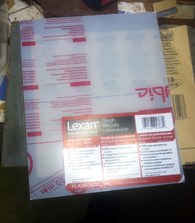
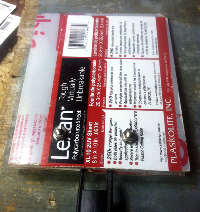
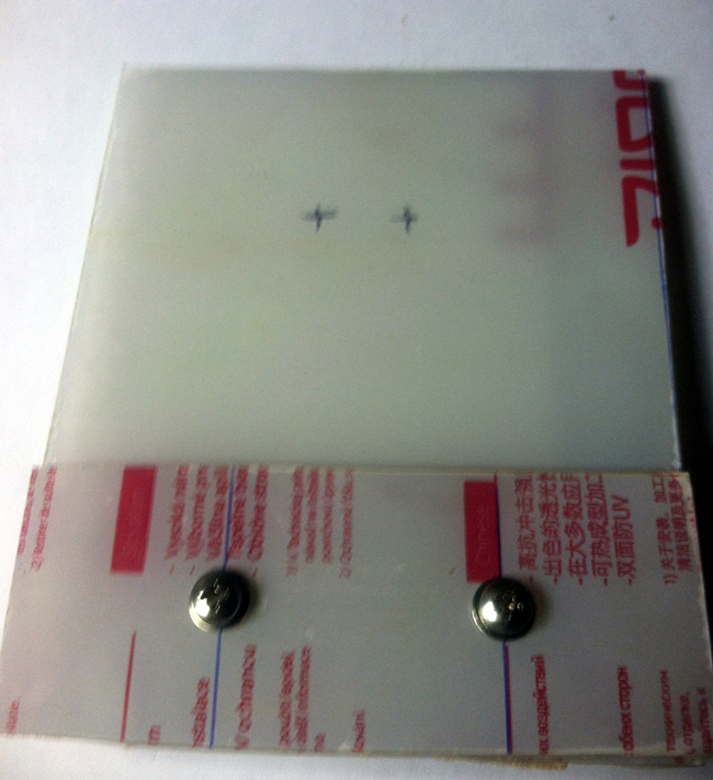
Let's start with an 8" x 10" Lexan sheet from Lowe's (about a $5 item.)
Split the Lexan into two 5" x 8" plates.

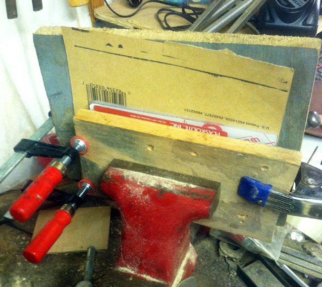
Peel the protective coating off one side of each plate. Apply a thin coating of two-part epoxy to one plate, join the two peeled sides together, clamp the two tightly and leave overnight to dry. This will produce a two-layer Lexan laminate, very strong, and very rigid.
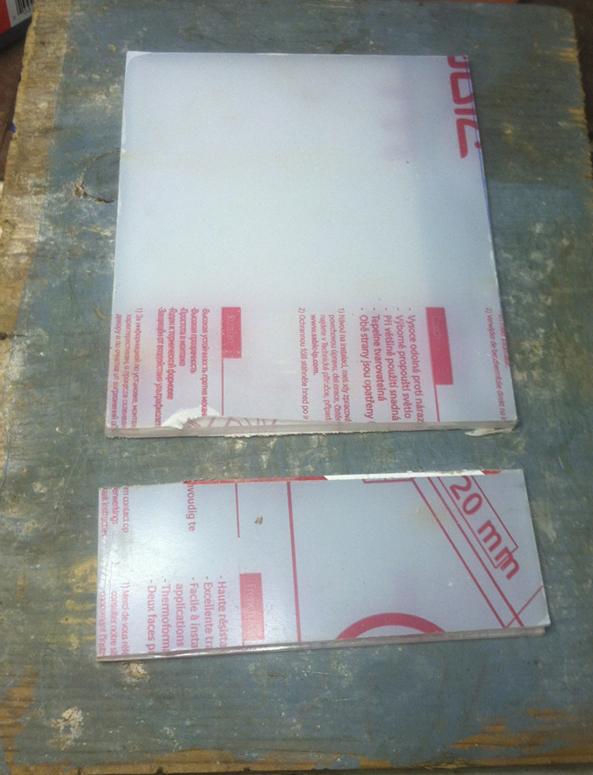
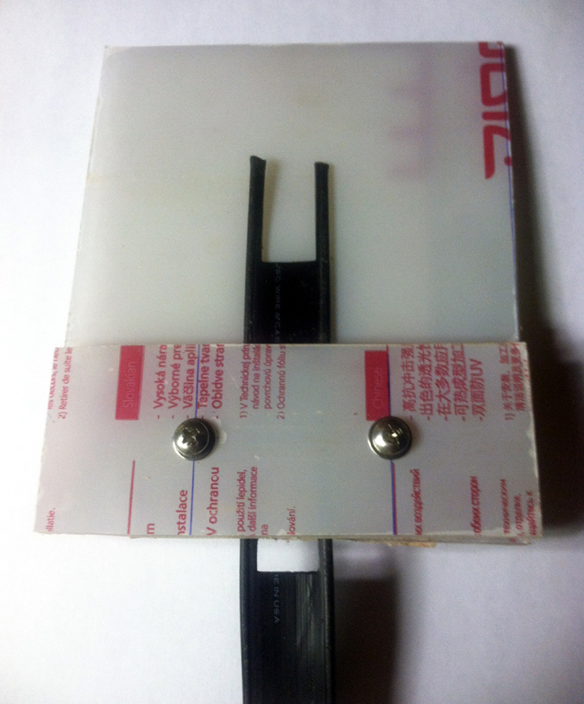
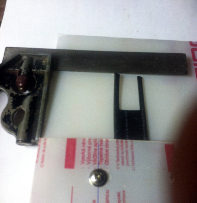
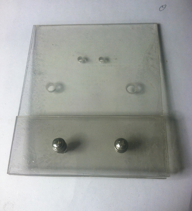
Cut off a strip about 2" tall strip off the 8" side, leaving you with two laminate panels, one 5" x 6", and one 2" x 5". See the next picture for an illustration.
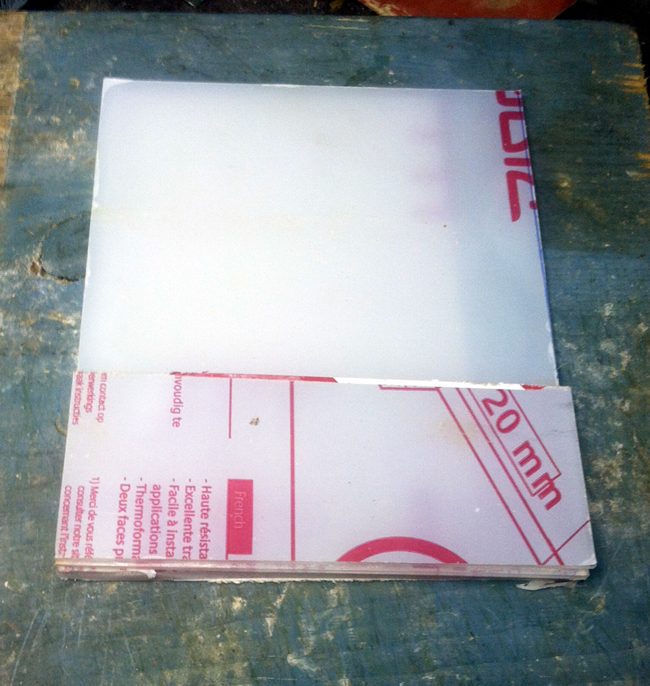
The bottom strip, laid on top of the larger plate, will act as a clamp to hold the ladder line in place.
Find the exact center of the bottom strip, and use that reference point to mark the future home of two screw holes that will hold the ladder line firmly in place.
Lay a piece of ladder line under the short plate, mark and drill the two holes in both plates. Remove the ladder line, and attached the bottom plate to the larger plate with two machine screws and nuts, putting a flat washer under the screw head, and a flat washer and a lock washer under the nuts on the other side.
Using the end of a ladder line as a guide, mark where the end of the ladder line wires will be.
Drill two holes, one at the end of each ladder line wire.
Drill two additional, slightly larger holes (as shown below) that are big enough for a piece of insulated, 12 gauge stranded wire to pass through easily, with as little extra wiggle room as possible.
Disassemble the two plates, peel off the rest of the protective paper, and reassemble. Your center insulator is finished, and should look very similar to what we see below. This is light, strong, and will be less visible than some opaque insulator.
Now with the center insulator finished, let's prepare the ladder line.
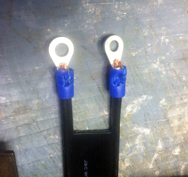
Get 31' of either 300 ohm or 450 ohm ladder line. Attach an eyelet to the end of each lead (the hole in the eyes should be the right size to just fit the two screws you'll use, i.e., the same size as the two holes you drilled in the insulator earlier). Solder to eyelet after crimping to ensure a firm electrical connection.
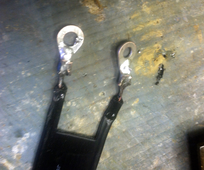
Upper end of the ladder line is finished. Let's start the lower end.
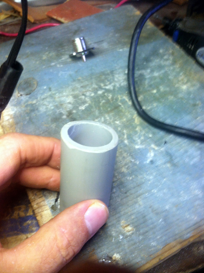
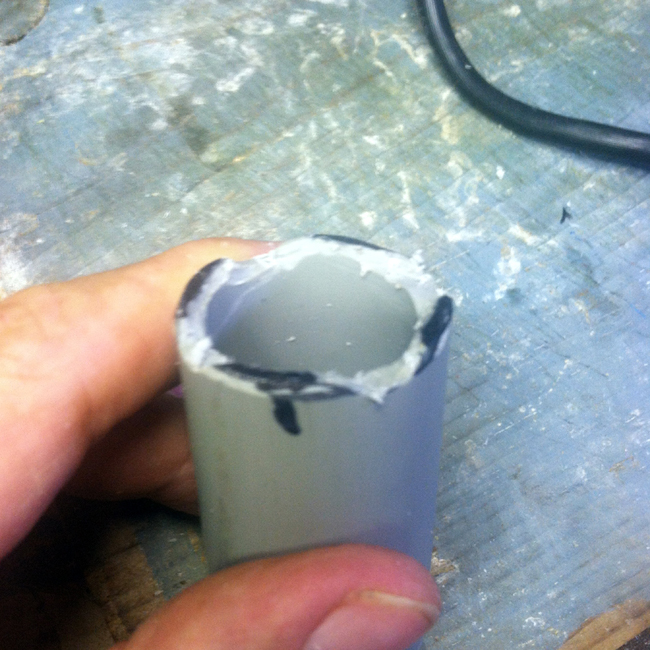
Get a female SO-239 connector, and a short piece of PVC pipe it will sit in. Notch the pipe so the connector will seat flush in the pipe end.
Now we're going to tie the whole ladder line thing together.
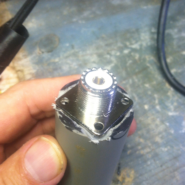
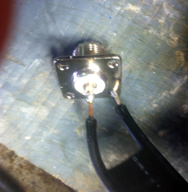
One end had eyelets on it. Take the other end, thread it through the pipe (enter through the smooth end, exit through the notched end), and solder the two leads to the SO-239 jack. One goes to the center connector, the other to the housing.
Slide the pipe up so the jack sits flush in the end. Mark four holes, one under each hole in the jack plate. Drill a hole at each mark, wide enough so a strong cable tie will pass through. (See photo below.) Pass one cable tie through each hole in the pipe, and the corresponding hole in the jack mounting plate. Pull the four cable ties snug, snip off the excess, and it should look like this:
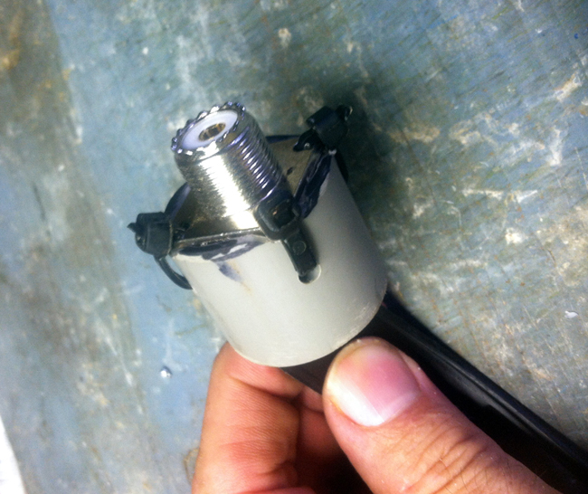
We're almost done with the ladder line. We want to seal off the inside of the pipe so moisture does not get to the jack inside. Wrap masking tape around the little openings where the mount plate doesn't quite meet the pipe. Wrap it so all openings are taped over. Prop the pipe up, jack pointed down, ladder line pointed up, and center the ladder line in the pipe. Mix a lot of two-part epoxy, and fill the inside of the pipe with the epoxy. Make sure it's not leaking out of the masking tape. Let the pipe stand without moving for two days. After two days, remove the masking tape, and you now have a sealed, weather-proofSO-239 jack on the end of your ladder line.
The ladder line is finished.
Next, we connect everything, and we'll have an antenna.
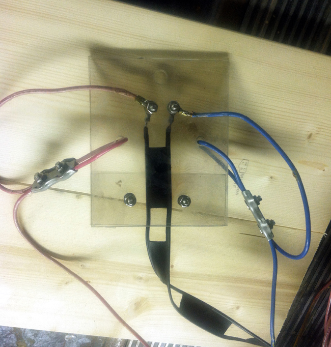
Take a 51' piece of wire (I used stranded copper wire, insulated, 12 gauge) and attach one end to the center insulator as shown below. In the photo, one 51' wire is blue, the other 51' piece is red. No real reason for the colors, other than these wires were salvaged from something else, and these are the colors they happened to be. Note that the wire passes through one hole in the insulator, is clamped to itself, and then connects to the ladder line screws above.
You an use almost any sort of wire for this. The larger the diameter, the more signal it will absorb. If it might touch a tree somewhere, use insulated wire. If it will be free standing in the air, bare wire is fine.
Don't get hung up on matching my materials. Use what you have, and as long as you choose non-conductive materials for the insulators, you'll be fine.
The only critical points to match are the length of the two wires and the ladder line. The online descriptions vary slightly on their descriptions, so do your research, and choose your own length if you'd like. Normally, the lengths will be in the ballpark of what is used here, but their are lots of variations that work depending on the result desired.
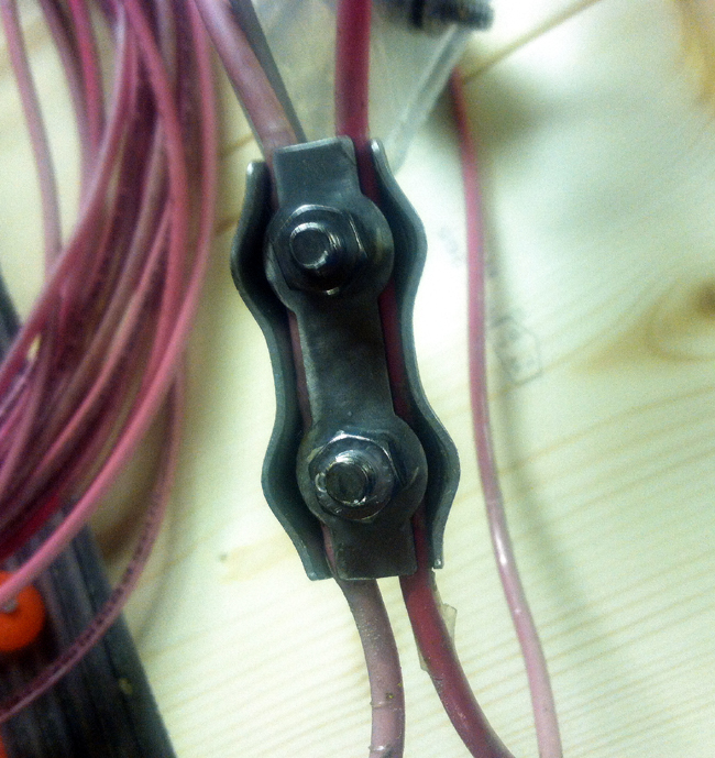
The nifty little clamps are called rope clamps. They come designed for different diameters, and you should buy clamps that fit the diameter of your wire. These particular clamps are designated as fitting up to 1/4" rope. You can buy these at the local hamfest from a wire vendor, but be careful. The vendor at the Huntsville hamfest was selling these for $18/pair, and since you'll need four of these, that can wreck your budget. You can buy four of these off Amazon or eBay for less than $10 total, including shipping, so shop for price. These are also referred to as "duplex" clamps, since they have two screws. Be sure to get the duplex style.
Note how the two screws pinch the wires, and they are NOT coming loose.
Now we have our ladder line clamped at the bottom, and the ends attached to the two terminal screws. The 51' wires are looped and clamped, and also attached to the same two terminal screws.
The extra hole at the top is where a supporting rope can be attached to the center insulator.
The last step is to attach the insulators to the end of the 51' wires, and we'll be ready to hand our new antenna.
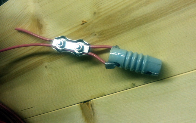
Again, we use rope clamps to secure the ends of the wire to itself. I wrapped the wire itself with a little duct tape to prevent rubbing where the wire passes through the dogbone.
That's it. Done.